Electroplating 3D Prints
Introduction
This project explores the fabrication of custom parabolic reflectors using 3D printing and copper electroplating. It combines the speed of additive manufacturing with precision metal finishing, offering a versatile pathway for rapid prototyping.
Each step, from CAD design to final assembly, was optimized to ensure structural integrity and high-quality RF performance. This blend of digital design and hands-on engineering showcases the potential of hybrid fabrication techniques.
CAD Design
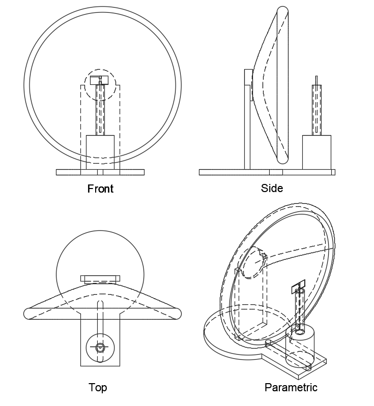
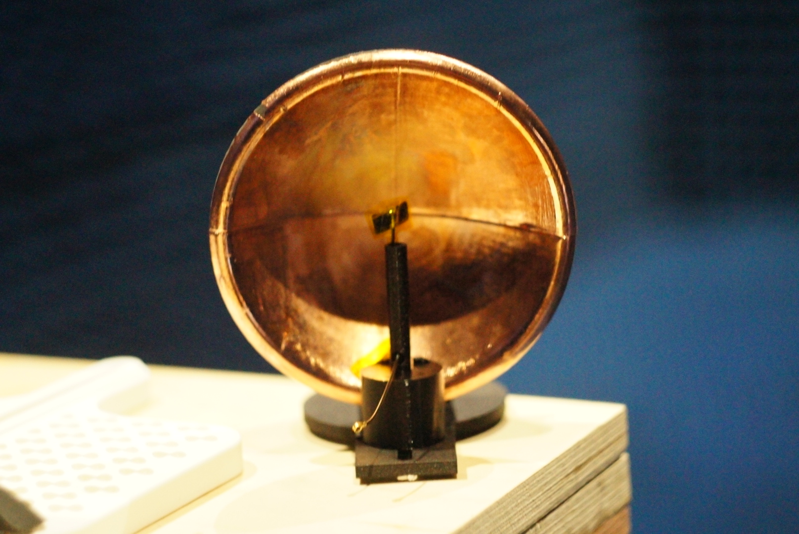
The reflector was meticulously designed using CAD tools to replicate the contours of automotive headlight reflectors. Focused on achieving optimal directivity and feed alignment, the design balanced compactness with performance.
Exported STL files preserved intricate design details, ensuring printability and dimensional accuracy crucial for subsequent stages.
3D Printing
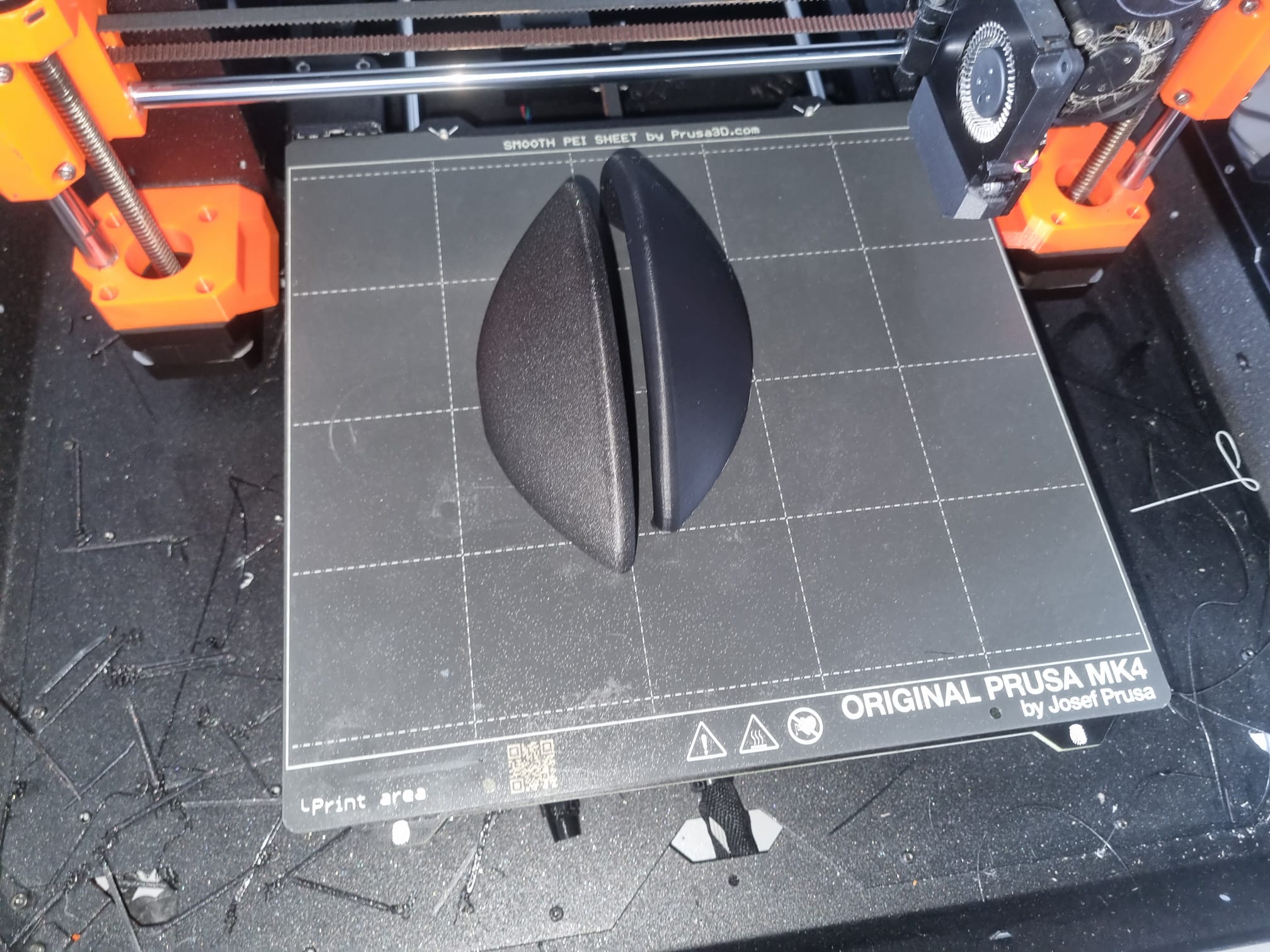
The reflector was 3D printed using FDM technology with a 0.4 mm nozzle and 0.2 mm layer height. PLA filament was selected for its reliability and ease of post-processing, ensuring stable geometries and smooth surfaces.
Print orientation was carefully optimized to reduce visible layer lines, enhancing both aesthetic and functional qualities of the reflective surface.
Post-Processing
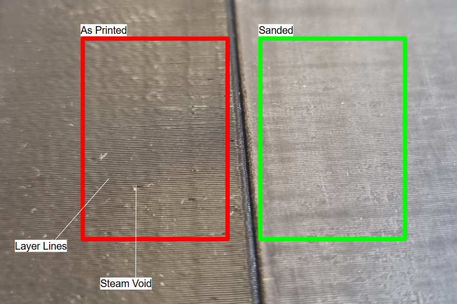
The printed parts underwent thorough sanding with fine-grit paper to remove surface irregularities, followed by cleaning with isopropyl alcohol to eliminate debris and oils. A degreasing bath ensured an ultra-clean surface for the next step.
Post-processing is critical to achieving a smooth, conductive surface, essential for high-quality electroplating and optimal RF performance.
Conductive Coating and Electroplating
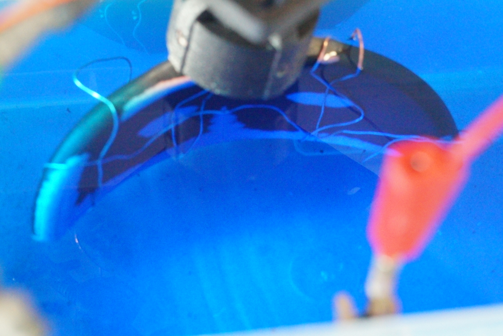
A carbon-based conductive spray was evenly applied to the sanded surface, establishing an initial conductive path for copper electroplating. The plated layer, deposited in a CuSO₄ bath with sulfuric acid and chloride ions, achieved a thickness of 20–25 μm.
The reflector was mounted on a rotating jig to ensure uniform coverage. After plating, the part was rinsed and dried, resulting in a highly conductive, professional-grade surface ready for RF testing.